Process


  • Core Assembly
  • Winding
  • Core Coil Assembly
  • Drying
  • Final Assembly
  • Testing & Inspection
  • Painting & Dispatch

Core Assembly

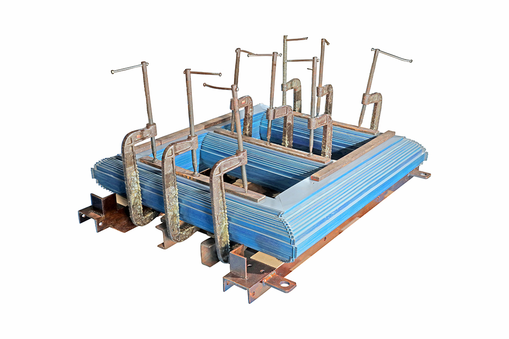
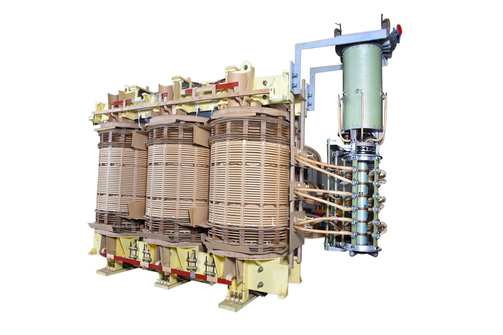
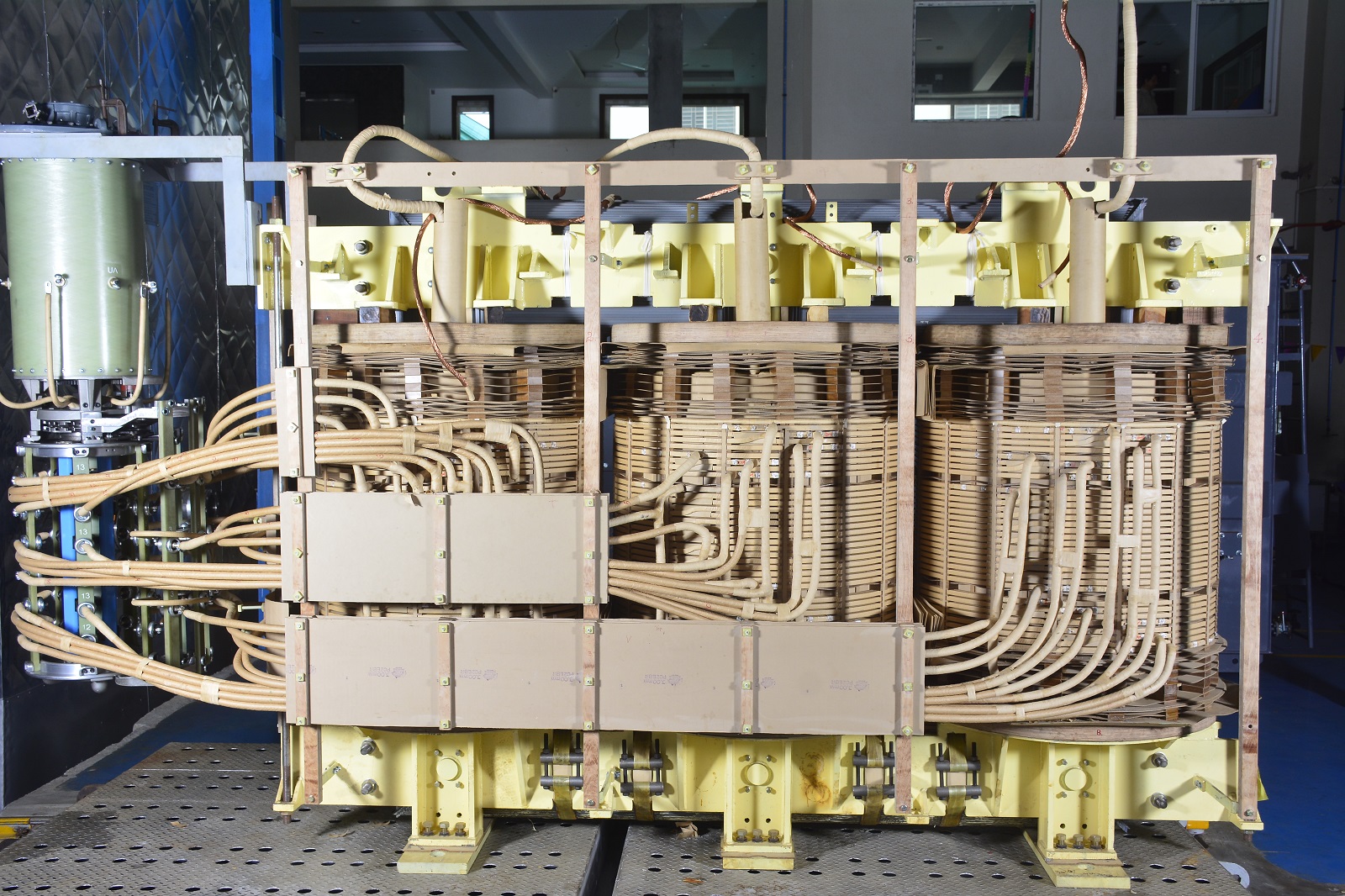
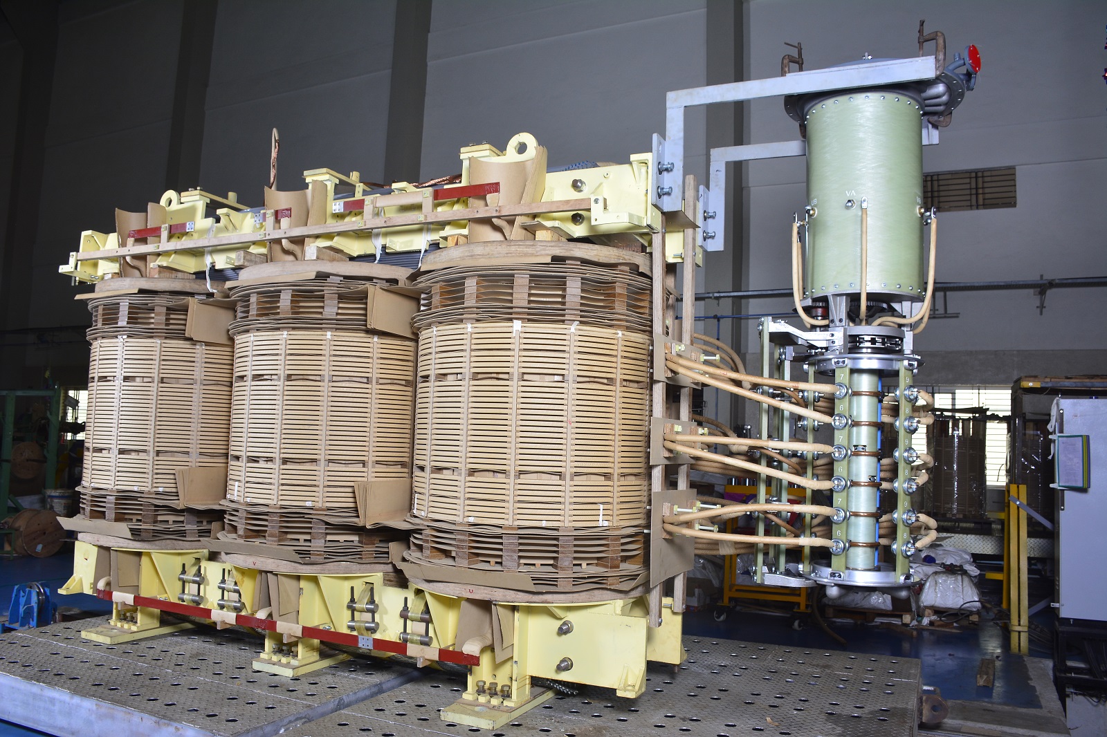
This is the main assembly frame. The assembly consists of the core, clamping structure, Feet, and the supporting structure for the framework to support tap and line terminals.

The core plays a vital role in selecting the material. The core material is manufactured from Cold Roll Grain oriented silicon steel sheets, available in various thickness and grades. The grade defines the material lost per kilogram while energizing the transformer. The increasing tariff of power has compelled manufacturers to build economical transformers and also design them for optimum losses.

The core mitered and assembled in step lap formation. The mitered joints are provided with minimum gap.

The clamping structure is a fabricated steel frame made from standard IS angle, channels or plate construction. The frame is held vertically and horizontally using tie rods. The vertical tie rods also exert adequate force on the coils during clamping to counter the stresses generated during operation. The transformer rests on its feet. The clamping structure supports the framework to route tap and line terminals.

Winding

The main components in a transformer are the primary and secondary windings. The windings are manufactured from electrical grade high conductivity copper and aluminum materials.

The winding conductor is drawn to various sizes in round and rectangular shapes. The choice of conductor and insulation covering depend on the voltage class, current, cooling and insulation clearances.

The cross section of the winding provides the necessary area to handle the current. The conductor is wound into coils. The coils are formed in any of the following shapes:

1. Helical or Spiral windings

2. Multi turn Bobbin type

3. Single coil multi turn

4. Disc winding continuous type, split type etc.

The coils are transposed during the winding to maintain low eddy current loss.

The winding is designed to provide adequate space for cooling in the form of ducts. It is desirable to ensure the surfaces are exposed to cooling. The oil flow in the ducts shall be free without any obstruction. The end of the winding is the terminals for end connection. The end connections are sufficiently free and long for making the connections by brazing.

The windings are supported on insulated cylinders to ensure proper handling during assembly, besides providing insulation.

Core Coil Assembly

The core coil assembly (CCA) is the winding assembly on the core. This is a vital part of the transformer also known as the active part.

The construction of the CCA is significant from the performance point of the transformer. The CCA defines the insulation scheme, cooling, dynamic withstand capability, handling. Insulation scheme is categorized into major and minor insulation. Major insulation addresses the capability to withstand high voltages, isolation of the primary and secondary winding, clearances for voltage withstand. Minor insulation is the turn insulation, joint protection etc. Both the major and minor insulation are equally important for the successful operation of the transformer.

Cooling is essential to prevent the thermal degradation of insulation. This enhances a transformer’s life. Transformers are cooled by convection or forced cooling. The cooling system is responsible for the free flow of oil in the assembly absorbing the heat generated by the windings and dissipating it. Transformers are designed to optimally excavate the heat from the windings through the gaps in the windings. This helps the transformer maintain the same levels of winding temperature and oil temperature during the loading cycle.

The transformer experiences dynamic forces due to frequent loading and unloading. The sudden loading and withdrawal of load creates a tensile stress on the winding in the form of buckling forces or bursting forces. The construction of the CCA by providing sufficient radial and axial supports prevents the stress from causing any damage to the windings. Clamping of the windings axially is necessary to hold the assembly firmly. Clamping structure of the assembly has supports to route the tap and line terminals. Insulated vertical and horizontal strips of adequate thickness of a frame work to assist the routing of terminals.

The assembly also provides facility to handle for ease of lowering the assembly into the tank and vice-versa.

Drying

This is a very important process in the manufacturing of transformer. The transformer undergoes drying process at various stages depending on the rating and voltage class. Drying is essential as significant part of the insulation used in the transformer is paper and wood based. The insulation material has high affinity to moisture which may weaken the insulation properties and reduce the insulation resistance to high voltages. This causes failures in the form of flashing at high voltages.

There are two types of drying: Air drying and Vacuum drying. Air drying is used in distribution transformers limited to voltage class below 33 KV, while Vacuum drying is predominantly used for all power transformers of voltage class above 33 KV.

Tank Assembly

The enclosure on a transformer is generally referred to as tank. This is a fabricated structure constructed of mild steel of adequate thickness to form a rectangular shaped tank. The tank has two main functions: i) hold the CCA with proper clearances for voltage and oil flow. ii) facilitate cooling, safety and maintenance. The tank must be leak proof, and should withstand pressure.

Final Assembly

The CCA is inserted into the tank assembly. All clearances inside are checked. The CCA should stand freely inside the tank. The primary and the secondary terminations are brought out through porcelain or epoxy cast bushing insulation. Tap Switch connections for external operation and or OLTC connections to the insulated board are provided on the tank. Handling, jacking facility to lift the tank assembly or jack it for fixing detachable rollers is provided. The transformer tank is fitted with valves for oil filling, filtration, oil sampling, draining. Provision for safety devices like Buchholz relay, pressure relief valve, temperature recording and control instruments, neutral current transformer, protection and instrument transformer are available as customized features. To ensure excessive pressure does not cause any damage conservator is provided for oil expansion and contraction during the operating cycle. In case of OLTC separate conservator is also provided, in the main conservator. Terminal identification are done on the bushings.

Testing & Inspection

All transformers manufactured are subjected to 100% routine testing as per IS 2026 and IS 1180. Test reports and certificates for each KPRS transformer are made available to the customers.

Painting & Dispatch images

All transformers are coated with a final coat of finish paint before delivery to the customer. The transformer tank is primer coated. The finish paint is generally shade 631 admiralty gray as per IS 5. Other color of finish paint is applied if the customer specifically mentions it in the purchase order. Extra paint for touch up is given on request. The transformer is dispatched to the customer destination as per agreed terms.